The base angle of the mold seems to be a very simple problem, but even the brothers who are now too experienced in mold design to work hard, may have had large or small problems because of the base angle.
A cube has 6 faces, and a set of ordinary molds has 6 faces
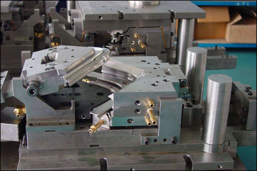
The mold is installed on the injection molding machine. The side where the product is taken is the operating side, the back of the operating side is the non-operating surface, the top is the sky side, and the bottom is the ground side. The right-angled side formed by the ground side and the non-operating side is the mold Base angle.
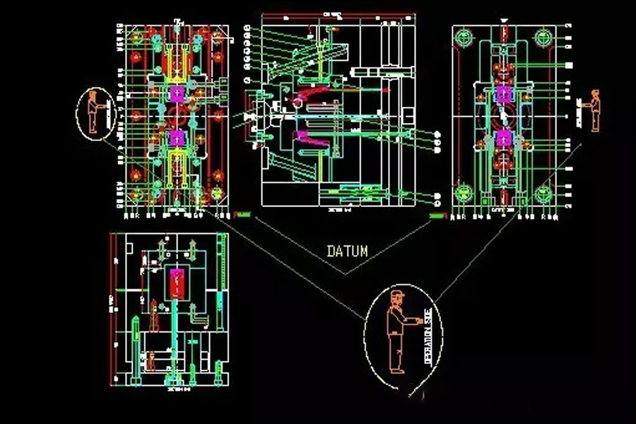
There is generally nothing wrong with the distinction between the base angles of the mold. As far as we are concerned, when we order the mold base, we usually ask the mold base factory to cut C10 chamfers on the base corners on all templates. There was such an error last year: when the designer ordered the mold base, the position of the reference angle in 3D was correct, and the mold base factory processed the base angle, but when cutting the base angle, it was reversed, and To the opposite side of the base angle. The position of the reference angle in the diagram formally sent by the designer to CNC for processing is not in the position in the mold ordering diagram (I don’t know the situation of Shenma). Die People Magazine WeChat: The reference angle of the mold blank 2D processing drawing sent to the mold room by mojurenzazhi is placed in the wrong position, but the position of the pendulum is not on the wrong corner cut by the mold blank factory. The mold is based on the reference angle. One-sided access processing. The deep hole drill only checked the chamfer on the template and the reference on the picture when drilling thimble and transporting water, and then the screw water transport thimble was all wrong. In short, this is a mess, such a mess, the head is big , Quarrels, scolding, and fights were useless. The problem was still to be solved. Later, the mold was changed back by the designer, and the template was drilled with holes. The above may be very messy, but I just want to say that the benchmarks cannot be arbitrarily placed, cannot be guerrillas, cannot be shot to change a place, and must stick to their posts from beginning to end, so that the work of the production troops can be guided smoothly.
Speaking of mistakes, reviewing mistakes is summing up experience and lessons. Once mistakes will be pointed out by thousands of people, how can I forget them?
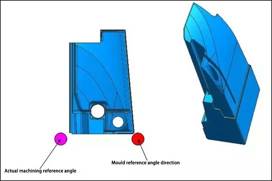
There was a problem that the position of the reference angle in my 2D machining drawing was unreasonably set. First look at the picture below.
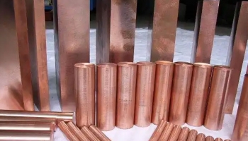
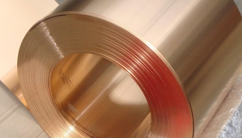
If it is based on the assembly datum of the mold, then the datum angle of the insert is on the right. It can be seen that the shape of the insert is not very regular. And I just remembered that it must be the same as the mold datum, and it must be unique, so I put the datum corner on the right, and the 3D code is also typed here. The actual fixed material is about twenty wires larger than this shape, and it is still beryllium copper, expensive! The material returned is square and polished according to the size of the material. First CNC gongs, when gongs are processed with the right-angled sides on the left side of the part. Then line cutting. The line cutting is made from the 2D drawing we copied, according to the reference angle position in the drawing. After the two processes are processed, the processed part is about 20 wires smaller than the drawing size. The main tube hole is also line-cut, everything is off, and the welding cannot be burned. Moreover, the welding performance of beryllium copper is not so good. When heated, it will be a big pile. Even a little welding will burn out. Then there is a big bag. Because of misunderstanding, there is no solution, and the final result is refueling. But experience must be accumulated, and lessons must be learned.
1. The Number And Processing Method Of The Mold
Generally, according to the internal requirements of the mold factory, the base angle is single-sided and four-sided. At present, there are a little more mold factories that may use the number of four-sided points to process. I think that the accuracy of the four-sided points is high, but it is more troublesome to touch twice. However, there are also some well-known mold factories that use the reference angle for unilateral processing regardless of the size of the mold. They say that the things they make are also very precise. Therefore, the four-sided score and the benchmark one-sided are better, no comment, and strictly follow the company's internal requirements. It is definitely correct.
2. For Mold Parts
If the side that is consistent with the reference angle of the mold is a right-angled side perpendicular to each other, it must be used as a reference.
3. If The Part Is Abnormal
But the shape still has a right-angled side, use this right-angle as the processing reference angle
4. If The Part Is Abnormal
Without any right-angled edges, you can cut a mutually perpendicular edge at the bottom. The datum is processed before processing, CNC gong or line cutting.
In addition, I would like to add that the part in the picture above is a push block with a slope around it. In fact, I personally think that it doesn't matter if the reference angle is not used for this part. The slope of the surroundings is a slope, or it can be divided into four sides. Pasting the picture is just an idea.
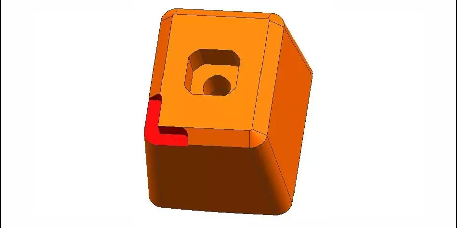
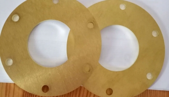
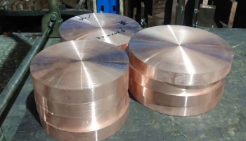
5. The Shape Of The Insert In The Picture Below Has A Slope
So cut out 2 mutually perpendicular red faces as the basis of counting.
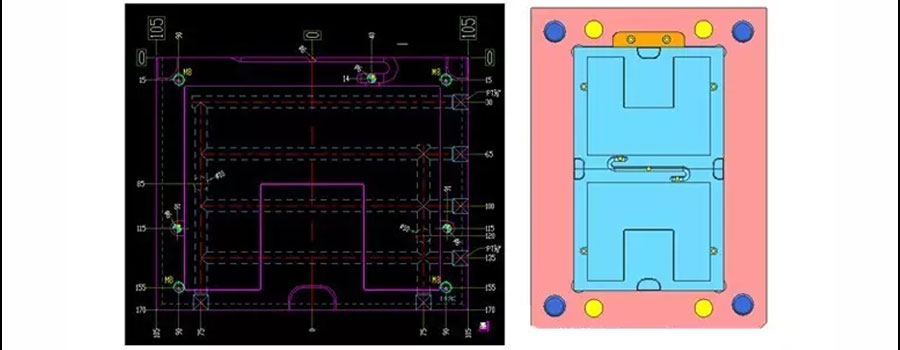
6. Look At The Picture Below
The mold core is divided into two pieces, and the mold is processed by dividing the numbers from four sides, so when we produce the 2D processing drawing, it is divided into two sides and one side is one-sided, instead of dividing the mold core. in.
From the picture above, it seems that there are few sealing positions for this mold, and the distance between the mold core and the glue position is very close. In fact, we initially left a sealing position of about 20mm. After the mold blank steel material was set, we said to cancel, and then we said no to cancel. First pause. After a few tossings, the appearance of the sent product became larger. , Only use the previous mold blank steel material. Anyway, it's also a plane model, so don't be afraid.
Summary
When we are designing and making molds, we must ensure that the design 3D, CNC machining access, milling machine, deep hole drilling, wire cutting access and other processes have the same and unique access positions. Reasonably arrange working procedures and choose processing benchmarks reasonably. The assembly datum of the mold is always fixed. Even if your machining datum does not match the mold datum, under normal circumstances, the assembly datum and the machining datum will not be installed incorrectly due to the misalignment. But when designing, it is necessary to consider as much as possible, and try to avoid incorrect installation. For example, the guide post on the reference angle side of the standard mold base is asymmetrical with the other three guide posts, and some are 2mm if they are slightly offset by 3~5mm. The purpose of this It is to avoid the deadly destruction of the mold when the mold is installed at 180°.