Wear resistance when the base material is self-matched or self-matched with various metals
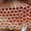
When metals stick to each other in sliding contact, wear occurs. This is especially important when considering thread connections. If the surfaces stick during the connection process, they will be damaged during disassembly, leading to expensive repairs or replacements. For many applications, the ability to disassemble and reassemble connections is a valuable feature. An example where this is particularly important is the drill string. The tubular components in the drill string need to be connected quickly and safely, and assembled quickly and repeatedly.
How does abrasion happen
No metal is perfectly smooth, and all materials have valleys and ridges that form bumps. These rough surfaces are very small, and when they come together, they will produce a lot of local pressure, which is much greater than the total pressure. Under these conditions, certain material combinations can form bonds. In some materials, this can be controlled and purposefully done to form a strong weld without a heat-affected zone. In the case of threaded connections, this adverse effect is called abrasion, which can lead to thread damage, and in extreme cases, it will be completely stuck.
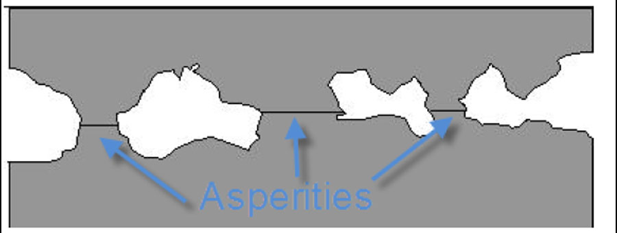
Asperities
In order to cause wear and tear, the interaction of materials requires pressure and direct contact between metal and metal, while heat acts as a catalyst. Different material structures have different wear trends. Some materials have protective oxides that can act as a barrier against wear. Materials also generate different amounts of heat, and emit heat at different rates. Another phenomenon is that one material may initially be clamped to another material, which acts as a protective layer. At first it seems that few direct factors will quickly merge into extremely complex interactions.
General wear rules
- Softer materials have a higher tendency to wear
- Liquids (including self-mating materials) materials that are 100% miscible in the liquid state are prone to wear
- Smooth surfaces produce more contact areas, generate more heat, and lead to higher wear trends
- Rough surface is prone to unevenness, which interferes and deforms and generates heat
- Materials with high work hardening rate have reduced wear tendency
- Materials with a high ratio of strength to elastic modulus have a lower tendency to wear
Strategies to prevent chafing
- Use grease as a barrier between surfaces while reducing frictional heat
- Make the connection slower and reduce the heat generated
- Use thread locking agent to avoid pressure and wear
- Surface hardening treatment (for steel)
- Use the coating to face the mating surface
- With two different materials
All these strategies are effective to varying degrees, but each strategy has a compromise. Using lubricating or locking compounds and reducing speed will have a negative impact on productivity. Case hardened steel sacrifices corrosion resistance. Coating will increase the cost and easily peel off. The combination of two different materials may be effective, but an additional set of material properties must be considered.
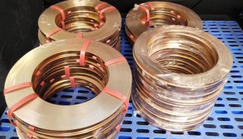
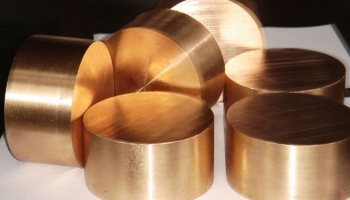
Wonder’s material
Two exceptions where self-crossing materials are prone to wear are ToughMet® 3 and 25 alloys. When used with themselves, they are not only resistant to abrasion, but they are also resistant when used with many other popular alloys used in well prospecting. These alloys have superior non-magnetic properties than other commonly used materials and have similar strength. They can be substituted or combined with other popular materials. The third alloy PerforMet™ alloy can also be used with other materials. However; it does not have good self-fitting anti-wear properties.
Wear test method: Because many factors affect wear, a material that wears out in one application may not be subjected to the same load in another application. Therefore, it is impossible to develop a general test that can be used to determine the material to be used based on the design force or pressure to be applied. Instead, a method called “button on block” was developed.
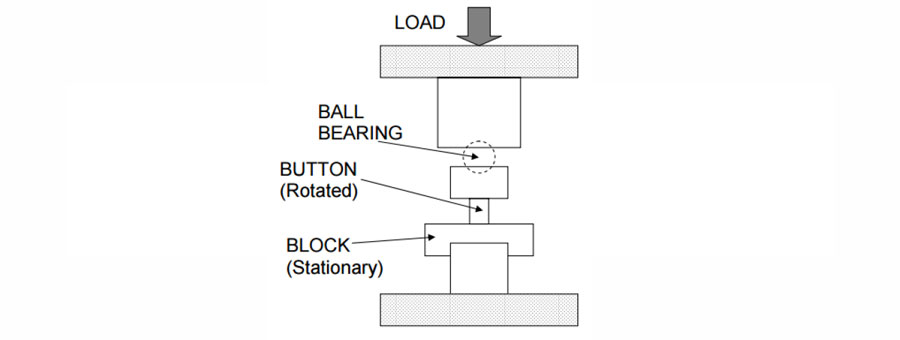
button on block
This test standardized the conditions and treated all material combinations the same. In the early stages of design, it is useful to select materials to be further tested in a specific application.
In this method, the button is placed on the block and rotated 360° under load. Then observe the two specimens under 10x magnification. Test and observe the new sample until wear is observed. After the wear is observed, the average value of the last applied pressure and the highest pressure at which wear is not observed is reported as the wear threshold pressure. The cross-sectional area of the button is used to calculate the pressure, even if the pressure is not necessarily accurate at low loads. In some cases, due to the interaction with the material properties and the nature of the test, one of the materials deformed severely below the yield strength. This does not necessarily indicate that the material will wear under this stress when the thread is in contact. However, this does make it impossible to obtain meaningful test results above this pressure. The following is a summary of Wonder’s wear results. The test has three possibilities: button deformation, reaching the load limit and wear.